The welding material consumption standards in industrial applications for boilers and pressure vessels and steel structures serve as essential elements for cost accounting and inventory management and production planning. Material waste and inaccurate cost control become possible when welding material consumption exceeds or falls short of established estimates by significant amounts.
This article introduces the core calculation logic, standard formulas, and practical reference tables used in mainstream welding processes, helping you quickly grasp precise methods for welding material consumption.
1. Core Calculation Logic
The calculation of quotas for all welding methods essentially follows the core principle of "theoretical filler volume + process loss factor," namely:
Actual welding consumables consumption = theoretical weld metal filler volume × (1 + process loss factor)
In simplified form:
Welding electrode consumption (kg) = Weld metal weight × 1.7
Welding wire consumption (kg) = Weld metal weight × 1.04
Flux consumption in submerged arc welding (kg) = Wire consumption × 1.7
Where:
Theoretical weld metal volume = Weld cross-sectional area × Weld length × Material density.
Process loss coefficient accounts for spatter, arc striking, arc extinguishing, slag/flux residue, etc.
2. Standard Formulas for Common Welding Methods
Different welding methods (such as manual arc welding, submerged arc welding, and gas tungsten arc welding) have different loss coefficients and calculation methods. The formulas for manual arc welding and gas tungsten arc welding are based on GB 985, while the groove dimensions for submerged arc welding follow GB 986, "Basic Forms and Dimensions of Submerged Arc Welding Grooves," to ensure that the quota calculation complies with national standards.
Basic Parameter Definitions (To be obtained from drawings / process cards)
Parameter Symbol |
Meaning |
Unit |
Remarks |
F |
Weld Cross-sectional Area |
mm² |
To be calculated based on joint type (butt, fillet, etc.). For submerged arc welding, groove dimensions shall be determined according to GB 986. |
L |
Actual Weld Length |
mm |
Excluding run-on/run-off tabs; typically add 10~15mm per end. |
P |
Density of Weld Metal |
g/cm³ |
Default 7.85 for steel welding materials; approximately 2.7 for aluminum and aluminum alloys. |
K |
Process Loss Coefficient |
% |
Refer to Table 1 below. |
Universal formula for theoretical filling volume:
Filling=F × L × P × 10-6 (kg)
Table 1: Welding Material Consumption Formulas and Loss Coefficients
Welding Method |
Material Type |
Actual Consumption Formula |
Loss Coefficient (K) |
Notes |
Manual Arc Welding (SMAW) |
Electrode |
Consumption = 2 × Filling |
20%–30% |
Efficiency depends on electrode type: Acidic E4303 (higher loss), Basic E5015 (lower loss). |
Submerged Arc Welding (SAW) |
Wire + Flux |
Wire = 1.18 × Filling |
8%–15% |
Flux = 1.25 × Wire consumption. Groove per GB 986. |
Electroslag Welding (ESW) |
Wire + Flux |
Wire = 1.05 × Filling |
3%–5% |
Flux fixed: 0.5kg/m + 0.4kg (start segment). |
Tungsten Inert Gas (TIG) |
Wire |
Wire = 1.25 × Filling |
5%–10% |
Minimal spatter, loss mainly from wire ends. |
Gas Metal Arc Welding (GMAW/MIG/CO₂) |
Solid wire |
Wire = 1.05 × Filling |
5%–8% |
Stable and efficient. |
Oxy-Acetylene Welding |
Wire |
Wire = 1.1 × Filling |
10%–12% |
Suitable for thin plates. |
For electrode consumption:
The formula “Electrode Consumption = 2 × Theoretical Fill” corresponds to a 20%–30% loss factor. In practice, this means the actual electrode consumption is about twice the deposited weld metal, resulting in a deposition efficiency of only 50%–60%. In other words, 1 kg of electrodes produces about 0.5–0.6 kg of weld metal. The consumption coefficient is calculated as the reciprocal of deposition efficiency: at 50% efficiency, the coefficient is 2.0; at 60% efficiency, it drops to approximately 1.67.
For flux consumption:
The formula “Flux Consumption = 1.25 × Wire Consumption” highlights that flux consumption coefficients are not fixed. For example, the commonly used factor of 1.7 is a conservative estimate that accounts for incomplete flux recovery, while 1.25 reflects an ideal condition with efficient flux recycling. In some cases, a different method is used, such as applying a fixed flux consumption rate of 0.5 kg per meter of weld, as noted in Table 1.
Special Note: Welding Material Conversion
If the welding method is temporarily changed during production, the material consumption quota can be quickly converted using the following coefficients:
Electrodes = 1.7 × Wire Consumption = 1.75 × Flux Consumption
In other words, the conversion ratio is:
Electrode : Submerged Arc Welding Wire : Flux = 1 : 0.6 : 0.9
The weld cross-sectional area is often the most challenging part of accurate calculation. Below are common industrial scenarios:
Fillet Weld (no groove, e.g., T-joints in steel structures):
F=0.5xK2 (K=leglength)
Example: K = 6mm → F = 18 mm².
Butt Weld, I-Groove (thin plates ≤ 6mm):
Example: δ = 5mm, root gap b = 2mm → F = 10 mm².
SAW Butt Weld, V-Groove (medium-thick plates):
Example: t = 25mm, b = 1mm, c = 3mm → F ≈ 276 mm².
SAW Panel Weld (no groove, thin plates):
Example: t = 10mm, B = 20mm, c = 3mm → F = 90 mm².
4. Practical Reference Tables
If manual calculation is not required, you can directly refer to the following quick-reference tables to obtain the welding material consumption per unit length (1 m) or per joint, covering common processes such as Submerged Arc Welding (SAW) and Shielded Metal Arc Welding (SMAW).
Table 2: SMAW Fillet Weld Consumption (Steel, P=7.85g/cm³)
Leg Size K (mm) |
Electrode Diameter (mm) |
Consumption (kg/m) |
welding rods(1kg) |
3 |
2.5–3.2 |
0.18 |
56 (Φ2.5) |
5 |
3.2–4.0 |
0.37 |
34 (Φ3.2) |
8 |
4.0 |
0.74 |
20 (Φ4.0) |
12 |
4.0–5.0 |
1.38 |
13 (Φ5.0) |
15 |
5.0 |
2.45 |
13 (Φ5.0) |
Table 3: SAW Butt Weld Consumption (δ = 10–30mm, V/X groove)
Thickness δ (mm) |
Wire Diameter (mm) |
Wire (kg/m) |
Flux (kg/m) |
10 (V-groove) |
4 |
1.26 |
1.58 |
20 (X-groove) |
4 |
1.97 |
2.46 |
30 (X-groove) |
4 |
2.75 |
3.44 |
Accurate Parameters:
Always confirm groove angle, root face, and root gap per GB 986. Include arc start/end length (~10mm each).
Loss Coefficient Calibration:
Perform test welds and weigh remaining material to fine-tune actual loss rates. For SMAW, adjust based on welder skill.
Special Materials:
For stainless steel, aluminum, or alloys, adjust density accordingly (e.g., aluminum = 2.7 g/cm³).
Welding material consumption standards need to be tailored to individual requirements because they do not follow a universal pattern. The combination of industry formulas with real-world calibration produces the most accurate results although industry coefficients and formulas provide dependable estimates. Manufacturers who understand these calculations and make process-specific adjustments will achieve better cost efficiency through waste reduction and optimized inventory management.
 Hot News
2026-04-09
2026-04-08
2026-04-07
2026-02-26
2026-02-19
2026-02-18

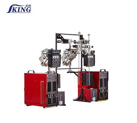
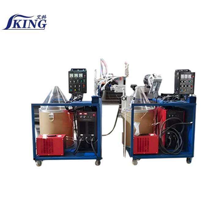
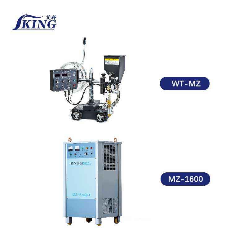
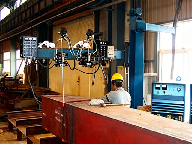
Since 1991, China IKING Industrial Group has been at the forefront of advanced welding technology. With a global presence and over 30 years of experience, we offer innovative solutions in submerged arc welding, electroslag welding, and stud welding. Our high-performance machines have empowered over 100 countries and key industries such as wind energy, shipbuilding, rail transport, and heavy machinery.
RM801-822, Hongxing Building 3, Linke West Road, Hedong District, Tianjin, China
Copyright © 2026 China IKING Industrial Group Co., Ltd. All right reserved Privacy Policy